Table of Contents
Horizon EME Getting Started Guide
| PLEASE NOTE - This is a public document. Any edits/updates to the document should not be specific to any particular site or installation. All edits/updates should apply to the system in general and be of possible benefit to all users. Information pertaining to specific sites should be added to the client site info pages for the site in question. |
|---|
| To ask questions, add comments or make suggestions about this guide please go to the related discussion section by clicking on the link at the top of this page. |
|---|
Welcome to the Horizon EME (Event Management Environment) Getting Started Guide. The purpose of this preliminary guide is to familiarize new users with the basic features of the system. This guide is intended to bring you up to speed on how to use the system for simple dispatching and call taking functions for one agency and one jurisdiction only. Coverage of multi-agency and multi-jurisdiction topics are left to later training once the basic functions covered in this guide have been learned.
This guide also covers single operator functions only. Additional features are activated in multi-operator environments. These topics are also left to later training courses. It should be noted however that in multi-operator environments all call details entered by one operator are immediately available on all other EM Center systems (as well as EM Mobile systems if present in responding vehicles). The system does support multiple operators working on the same or different calls at the same time by utilizing additional built in mechanisms to coordinate operator actions.
Finally, the EM Center system is designed so that all aspects of the system workflow are customizable by the user. The information below covers a sample configuration and workflow. As an example, the event and unit statuses and their allowable progression through a call may be different from your training system. This guide is intended to give you an overview of how a typical system would operate. You will be provided with more detailed instructions should areas or operational aspects of your system be different from those contained in this guide.
Section I – Accessing the System
1. Logging In
Logging on and off are generally done at the beginning and end of your shift, respectively.
- To Log-On to the EME Double-click on the EM Center shortcut on your desktop. You will see a login box with a spinning globe and STI logo. Enter your assigned username and password to access the system.
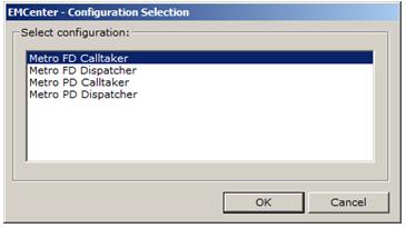
- You may be prompted to select a configuration at this time. If so select the appropriate entry in the configuration list.
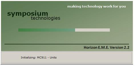
- The various components and modules of the EME will then be loaded and activated and the system will display a progress bar during this process.
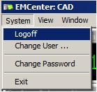
- Click on the System menu in the upper left hand corner of the main EME display
- Select the Logoff option
2. System Display
| NOTE - Your system may look different or be organized in a different way from the configurations shown below. The Horizon EME is comprised of a number of different components (event displays, unit displays, map windows, etc.) that can be organized and arranged in any way requested by the user. Even if your layout is different from the images below the functional overview contained in this document will still apply |
|---|
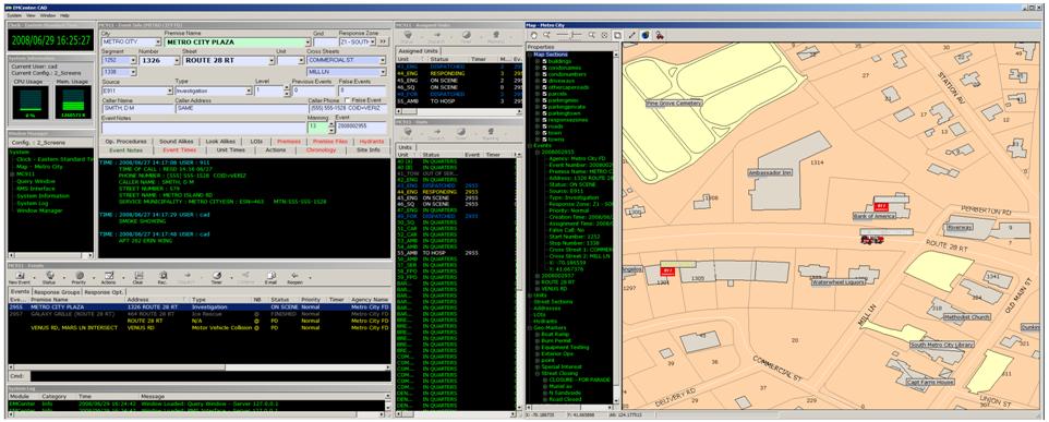
The EME typically uses a multi-screen layout. As well, the system uses a “flat format” type interface, so all important information is available at all times.
We will now look at how the system is used.
Section II - Call Taking and Dispatching
Call Taking and Dispatching answer two simple questions: Where and What. Where refers to where the event is located. What refers to what kind of event is involved, and what resources should be sent to deal with it.
An Example of a 2-Screen EMCenter configuration with the call taking screen on the left and the map on the right. Your system may be configured for more screens or have the windows organized in a different manner.
Automatic vs. Manual Call Taking
- With E-911, calls from landlines will automatically populate all the fields required to determine where the call originates from.
- If the call does not originate from E-911 (i.e. direct line or 3rd party company) or if the E-911 information is somehow inaccurate, you can manually enter the required information.
To enter the call information manually, follow these steps:
1. Create an Event
- Click on the New Event button, and select the agency for which the event is to be created (ie, “Metro City Fire”).
Using the New Event Button
The New Event button is located in the Event section of the main display. Clicking on it will enable you to create a new event. In the case where there is more than one agency or department, it lets you choose which one you wish to create the new event for.
2. Select a Jurisdiction
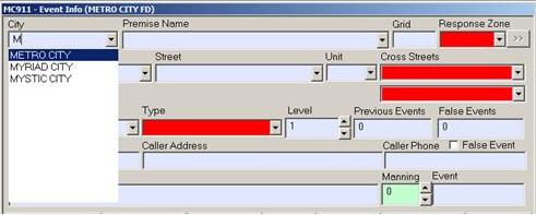
- Go to the city field, and select the town, city, or jurisdiction in which the event is occurring and type the first letters of the town’s name (“M” for Metro City). Hitting <TAB> will select it, and take you to the address information.
- Your system may be configured to set the city/jurisdiction automatically depending on the agency for which the event is created. If this is the case then you will be moved to the next step automatically.
The Jurisdiction Field
The Jurisdiction/City field is where you manually choose the city or jurisdiction you are dispatching the call from. If E-911 is present, this information is filled in automatically.
3. Set the Address
- Fill in the number, street name, and building unit (if applicable), in that order, using the <TAB> function to switch between fields. These fields also “auto-populate” like the City field, narrowing your choice as you type.
- Once you enter this information, hitting <TAB> will enter the information into the system, and tell you whether it is actually a valid address, and take you to the Event Notes field.
Setting the Address
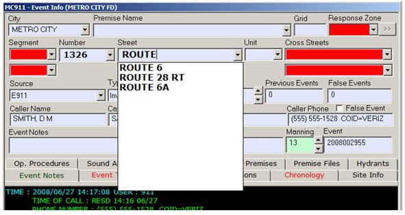
Here we see the Street field, where you enter the street component of the address. Like a number of fields in the CAD, the Street field has an auto-population feature – just start typing in the name, and it automatically starts narrowing down the choices.
After you have selected a street you can search the system for all the valid addresses along that street. Just drop down the street search window and start typing the number you are searching for. The system will display all numbers equal to and greater than the number you have entered.
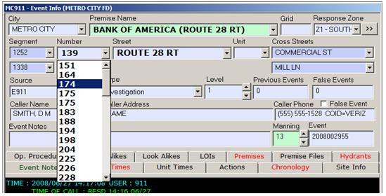
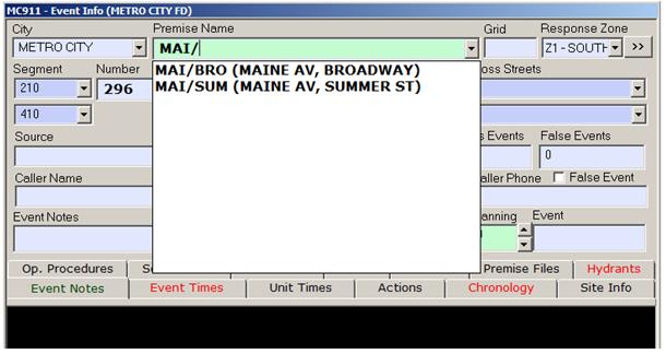
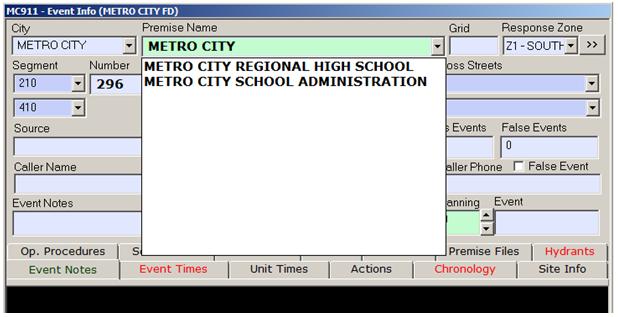
You can also set the address by searching for a location name. To start searching for valid locations in the jurisdiction selected you would start typing the first letters of the location you are searching for in the “Premise Name” search box. When you locate the desired location you can just select it from the list, hit the <TAB> key and the system will set that premise as the location of the event.
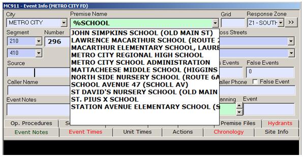
If you are not sure of the exact spelling of the name of the desired location you can do a wild-card search. You can enter the “%” character anywhere in a search field and the system will display all variances of locations that match the name you have typed.
The system also allows you to search for road intersections. To search for an intersection just type the first 3 characters of the the first road intersection followed by a forward slash “/” then the first 3 characters of the second road intersection name. Alternately you can search for intersections by typing the entire name of the first street followed by the second street. The system will automatically narrow down your search as you type.
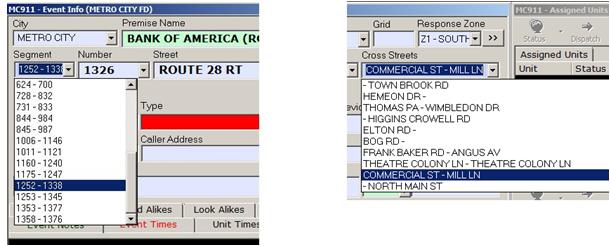
You can also search for a location by selecting a valid road address range or valid set of cross streets. Once you select this information, hitting <TAB> will enter the information into the system.
4. Verifying the Address -Valid vs. Invalid Addresses
- A valid address is one that exists in your city database, and can be plotted on a map; an invalid address is one that isn’t in your city database, and can’t be plotted.
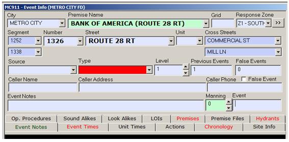
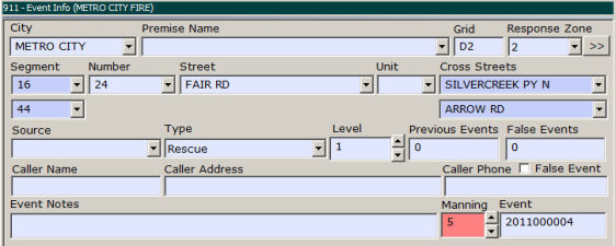
- If the address is valid, the EME will display the address (segment range) it falls between, the nearest cross streets, the response zone, and the grid reference.
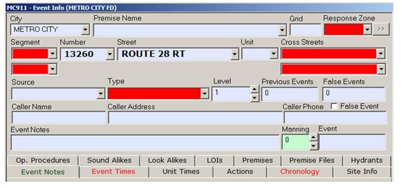
- If the address isn’t valid, the street segment, cross streets and response zone fields will all turn red, indicating that the location can’t be found.
- Responses can be dispatched to an invalid address, but the location-based info will not be available.
There are three specific levels of Validation that an address can fall into:
- Fully Validated (valid street address)
- Partially Validated (valid street segment, invalid address)
- Non-Validated (invalid street segment, invalid address)
Valid, Partially-Valid, and Invalid Addresses
When an address is valid, the Cross Street, Street Segments and Response Zone are displayed (as above). The premise Name field will fill in and turn green.
When an address is partially valid, everything will display but the Premise Name field, which will remain blank and blue.
When an address is Invalid, these fields display as blank and red (as below).
5. Entering Event Notes
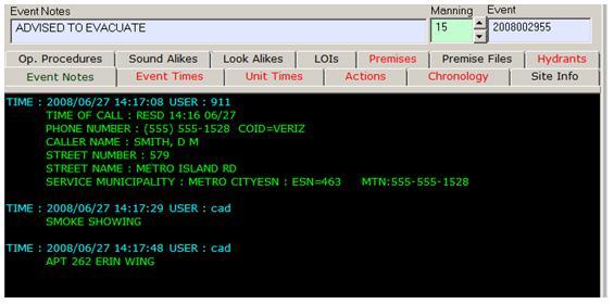
- To enter an event note, simply <TAB> or use the mouse to position the cursor in the Event Note field. Type your note, and hit the <ENTER> key.
Note: The system may be configured so you can cut and paste an existing event note back into the event notes field. This is done in situations wherein the same note needs to be repeated for another call, or any similar situation wherein copying is faster than typing it out again.
- To copy a note, highlight it in the Event Notes tab and click <CTRL> +C on the keyboard.
- To paste a note, place the cursor in the Event Notes field and click <CTRL> +V on the keyboard.
An Example of Event Notes Being Entered
6. Set the Call Type
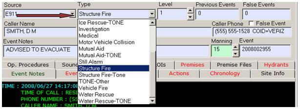
- Select whichever call type is appropriate. This is done by clicking the arrow next to the Type field, and selecting the call type from the list.
- At this point you have all the necessary “where” information to accept and dispatch the call.
The Call Type Menu
This is an example of a typical call type selection, from which you select the appropriate type. You can either choose the type from the menu or begin typing the name of the call type in the field, and the system will select the most appropriate.
7. Other Fields
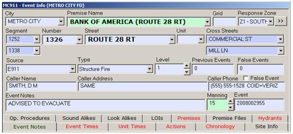
- The Source field refers to the source of the call, and can be filled in once the units are dispatched.
- Premise name refers to an alias that might be used for an address, such as “General Hospital”. In such cases, filling in the Premise Name field is quicker and easier than filling in the address info, and will have the same effect.
The EME Call Taking Section, with All the Fields Filled Out
8. Accepting the Call
- Click the Status button, and select “Accept”
You can also cancel the call
- Click the status button, and select “Cancel”.
Once the call is accepted, you can now decide what units should respond.
Accepting a Call Using the Status Button
The Status button is located in the Event section. To accept a call, click on the button, and choose the “ACCEPT” option from the drop-down list.
9. Recommending Units for Response
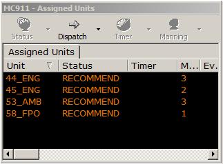
- Clicking on the Rec. button will prompt the system to select units for response.
- The selected units will change colour in the Units window (from green to orange), and will also appear in the Assigned Units window.
At this point you can review the selection and make modifications if required.
- While the Rec. button is active, clicking on selected units will de-select them. Clicking on units that were not originally selected will select them.
- Depending on the enabled options, changing the call type may change the vehicle recommendations.
An Example of Recommended Units
10. Dispatching Units
- Clicking on the Assign (or Dispatch) button will dispatch the selected units. Their status will change from “In Quarters” to “Dispatched”, and their colour will change from orange to blue.
- At this point the system will automatically send information about the call to the halls or personnel involved.
- Once the vehicles are dispatched you can begin managing the response.
11. Accepting the Call, Recommending and Dispatching Units in One Step
- This option saves a great deal of time, and is used when you are familiar and comfortable with the systems recommendations.
- To Accept Recommend and Dispatch, click on the Status button and select the Accept and Dispatch option.
12. Dispatching More Units as Required
- More units can be manually dispatched should the need arise, by simply making sure the Rec. button is activated, selecting the units in the Units window, and hitting the Assign (or Dispatch) button again.
- Increasing or decreasing the event level can also change the unit recommendation. To increase or decrease the level, click the up or down arrows next to the manning field, and assign the units that the system recommends.
Examples of a Change in Event Level
Clicking on the arrows next to the Event Level field enables you to change the alarm level (and vehicle recommendations) as appropriate.
Section III - Unit Handling
Once the units are dispatched, the system allows you to record and manage different aspects of the response
1. Changing Unit Status
- You can change each responding unit’s status as required. These statuses may include Enroute, Turn Back, At Scene, Clear, Returning, Out of Service, In Service.
- To change a unit’s status, make sure the Rec. button is not active, select the appropriate unit in the Units window, click the status button and select the appropriate status from the list.
- Note: Not all statuses will be available at all times, based on the current status of the unit.
- Note: Some systems are configured so that double-clicking on a unit brings it to the next status in the response progression (i.e., double-clicking a unit in “Dispatched” status would bring it it “Enroute”).
2. Specifying Manning
- The system enables you to record how many personnel arrive on scene. This can be done in two ways, to accommodate staff dispatched from halls, as well as volunteers arriving on-scene in their own vehicles.
- Once a unit is dispatched, select it and click on the Manning button in the Units window, and specify the number of personnel on the vehicle. You can also indicate specific personnel by clicking on the Crew feature.
- For those arriving with their own vehicles, simply click on the arrows next to the manning field to indicate the increasing or decreasing number as they arrive on scene, or depart.
- Once the required personnel for that call type are on scene, the manning field will change colour, indicating the personnel threshold has been met.
An Example of Changing the Manning on a Call
The arrow keys next to the manning field enable you to manually change the manning as required. In the example above, the manning field on the left is red – that means that the minimum manning for that call type has not yet been met. Once the manning threshold has been satisfied, the field turns green.
3. Using the Timers
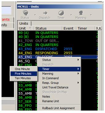
- To set a timer for a unit, click the Timer button in the Units window, and select the duration.
- To set a timer for an event, click the Timer button in the Events window, and select the duration.
Example of Setting a Timer in the Units Window
In the above example, the user is using the right-click function to set a timer. Instead of using the button, click on the unit or event you want to set a timer for and right click – then follow the menu options to find the appropriate timer.
4. Other Unit Settings
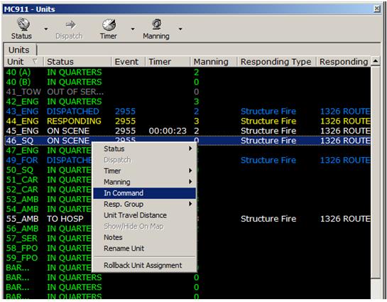
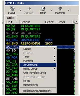
- To mark a unit “in command”, right-click on the unit in the Units window, and select the In Command option.
Setting a Unit In Command
When a Unit is marked in Command, an Asterisk (*) appears next to it in the Units and Assigned Units listings. In the example above, one vehicle is already marked in command, and we are choosing to switch command to another vehicle.
- To change the response group to which a unit belongs, right-click on the unit in the Units window, select the Response Group option, and assign the new response group.
Section IV - Finishing the Call
Once the last responding unit to an incident has returned to quarters, the event status reverts to Finished. At this point, you can finish up entering any data left outstanding, and can close the event.
- To close an event, select the appropriate event in the Event window, click the Status button, and select Close.
An Example of Closing an Event
Above, we see how the Status button is used to close an event, after all vehicles have returned to quarters. Some system may use shorter acronyms such as “CD” in the place of “Closed”.
Section V – Mapping
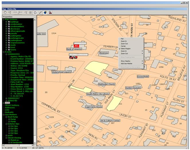
The Mapping section provides you with an at-a-glance understanding of ongoing events. To navigate around the map, use the Pan tool (click the “hand” button in the map toolbar), or use the arrow keys.
An Example of a Map Displaying the Response Scene
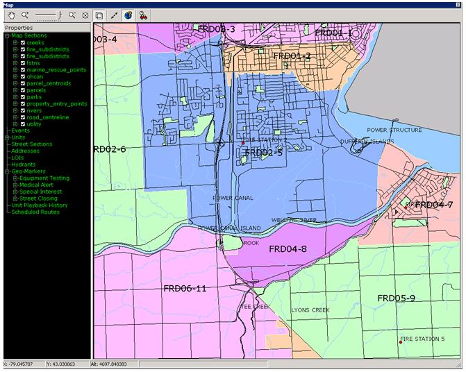
An Example of a Map with the Response Zones Color Coded
1. Verifying the Event Location on the Map
- Looking at the map enables you to quickly determine if the location provided by E-911 or the caller is correct.
- To verify the location of the event, use the Select tool in the Map Toolbar to create a box around the unit, zoom in, and verify the location.
2. Understanding Map Layers (especially Response Zones)
- Map layers refer to the different types of visual information and cues that are displayed on a map. A layer refers to a class of objects, such as hydrants, addresses or response zones.
- The system allows different layers to be turned on or off. Different layers are set to be visible at different levels of magnification, based on your needs. Different response zones are indicated by different colour codes.
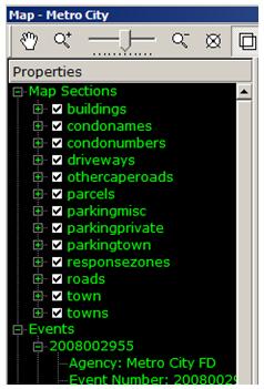
- To turn a layer on or off, go to the Properties window of the map, click the “+” sign next to map sections, and check the boxes next to the layers that you wish to display or hide.
An Example of Map Layers
In the example above, you can see the various map layers for a given city. These are located in the menu tree next to the map in the Map window, and can be navigated in several ways. Click the +/- to hide or show them, and check/uncheck the box to show/hide them.
3. Hydrants
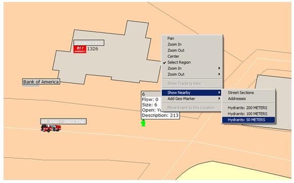
- To display hydrants around an event, zoom in to the event, position the cursor next to the event, right-click, and select the Show Nearby option; then, select the appropriate hydrant option.
- Red hydrants are closed, green ones are open. Right-Clicking on the hydrant and selecting the “Toggle Info” option will show or hide information about the hydrant, such as flow rate.
- You can also mark a hydrant as open or closed, examine properties such as flow rate by either right-clicking on the Hydrant itself on the Map, or choosing the appropriate hydrant from the list in the Hydrant Map tree.
A Close-Up Example of Hydrants on the Map, with the Information Toggled On
4. Moving a Call
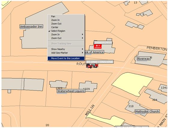
- If the location is not correct but is nearby, simply right-click on the area on the map you wish to move the event, right-click, and select Move Event to this Location.
A Close-Up of the Map, with the Move Event Option Highlighted
5. Finding Nearby Streets and Locations
- Zoom in to the event, position the cursor next to the event icon, right-click, and select the Show Nearby option; then, select the appropriate option.
6. Viewing Call Info on the Map
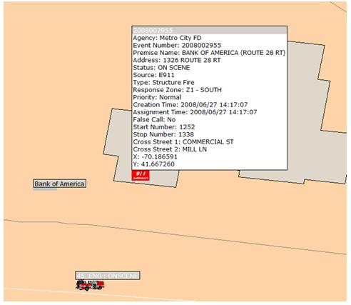
- Click on the “+” sign next to Events in the Properties window of the map, right-click on the event, and select “Toggle Info” to hide or display the event information.
A Close-Up of an Event on the Map, with the Information Toggled On
7. Activating the Pictometry View
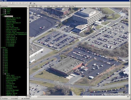
The Pictometry system provides photographic, scale-accurate aerial images of all municipal addresses in the US from a number of angles, greatly enhancing response capability. If your department has Pictometry images enabled, you can access them from the map by right-clicking and choosing the Pictometry option.
A View of the Map with Pictometry Enabled
8. Adding GeoMarkers
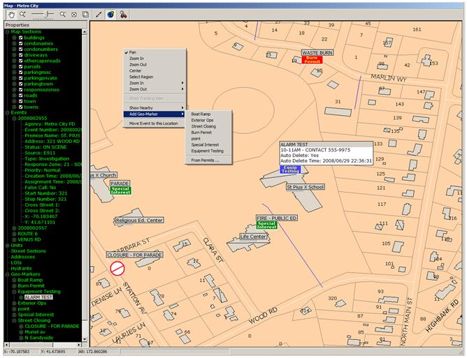
You may also be required to add geographic markers (Geo-Markers) to serve as indicators or reminders about events or conditions in your coverage area. By right clicking on the map at the location that you would like to add the Geo-Marker you can go the the “Add Geo-Marker” menu item section and select the Geo-Marker type you would like to add. You can then fill in the details such as the name, description and, if applicable, the auto-delete time for the Geo-Marker in question.
Your system may also be configured such that Geo-Markers are automatically added to the system from other integrated external databases or systems without requiring operator input. If this is the case then the Geo-Markers will appear automatically on your map screen and have their details listed in the Geo-Markers listing on the left-hand side details section of the map screen. You can also access the details of a Geo-Marker by right-clicking on it and selecting “Toggle Info”.
A View of the Map with a number of Geo-Markers Added
9. Adding GeoFences
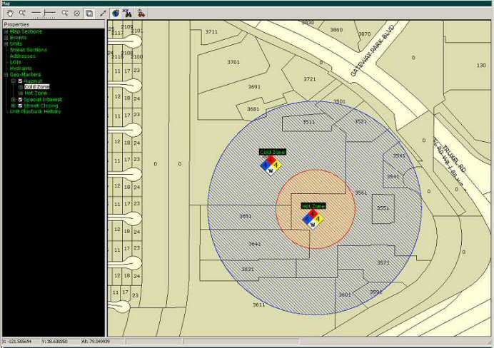
After you have added a Geo-Marker you have the option of then added a related GeoFence. GeoFences can be added to show the area of coverage that is related to the Geo-Marker. You can add a GeoFence by right clicking on a Geo-Marker, selecting 'Add GeoFence…' and following the instructions that appear of the screen.
A View of the Map with a GeoFence Added
Section VI – Review of Call Info
The system also enables you to review all information about the call, using the tabbed displays just below the location information. These tabs show when each status change, action, event note, and every other event-related entity was entered, and by who.
- Black tabbed displays mean there is no information in that specific tab. Blue tabbed displays mean that there is information in the tab, and red tabbed displays mean that the information has changed since the last time you looked at it.
Note: Some systems are configured so that tabs flash when new information is available.
- Tabs are accessed by clicking on them.
1. Event Notes Tab
- This tab lists all the event notes that were entered during the course of the call.
- Some multi-jurisdiction systems are configured so that the Event Notes tab will display a message if an incident location which shows as invalid is in fact valid in a nearby municipality.
- An event note can be highlighted and copied (CTRL C) from the Event Notes tab and pasted (CTRL Z) to the Event Notes field. This saves time when entering the same note for another incident.
2. Event Times Tab
- This tab lists all the event associated times for a particular call.
3. Unit Times Tab
- This tab lists all the unit-associated times for a particular call.
4. Actions Tab
- This tab lists all the actions that were taken for a particular call, and their times.
5. Chronology Tab
- This tab lists everything associated with the call, in the order it happened.
6. Query Window
- The Query window is a module that enables you to run detailed queries on a number of entities. These include locations (cities, streets, addresses, ect), as well as prior calls.
Section VII – Other Incident Functions
There are a number of other functions that are useful for the event management process:
1. Priority
- This function lets you prioritize calls as either normal, medium, or high priority.
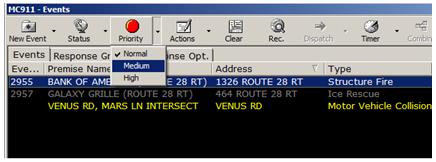
- To prioritize a call, select the appropriate event in the Events window, click the Priority button, and select the appropriate priority.
An Example of the Priority for a Call being Set
The Priority function can be combined with the Sort function to stack calls in order of priority. First set the priority of the calls, and then sort them by clicking on the Priority header. This will sort the calls in order of Priority (Ascending or Descending).
2. Actions
- These refer to different types of actions that can be taken during the course of an event that need to be recorded. Examples include outside agency notified, outside agency on scene, agency leaving scene, agency the event was left with, command benchmarks, medical benchmarks, and others.
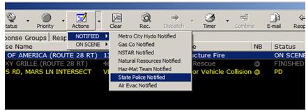
- To select an action, select the event in the Events window, click the Actions button, select the appropriate category, and select the appropriate action.
An Example of Selecting an Action
3. Combine
- Sometimes several calls can come in regarding the same incident, resulting in multiple events being opened for the same incident, each with different details and call numbers. The Combine function lets you store all of this information under one incident number.
- To combine two or more calls, hold down the <CTRL> key, select the calls you wish to combine in the Events Window, and click the Combine button.
An Example of Using the Combine Function
4. Email
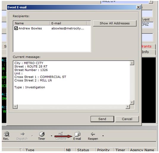
- The email function lets you send the event information to specified recipients. To send an email, select the appropriate event in the Events window, click the Email button, select the appropriate individual(s), and select Send.
An Example of the Email Dialogue Box
This is the box that you see when you activate the email function, where you select the individuals who are to receive the notification from the list provided.
Note: The system may be configured so that emails are sent automatically (or not), based on a whole host of situation-specific conditions. This is fully dependent on the needs of each particular client.
Note: The system may be configured so that the email notification box pops up automatically for certain call types, prompting you to send an alert email to the appropriate personnel.
5. Copy Event
When an event is highlighted and this option is selected, you can create a NEW event at the same location for another agency. This is important in situations where you are performing multi-agency dispatch (Fire, Police, EMS, etc.), and more than one agency needs to respond. When the new event is created, it is in the same location, but will have a different incident number, and may have different response group, vehicle recommendation, and other info. To access this function, highlight the appropriate event, click on the arrow section of the New Event button and select whichever agency you wish to copy the existing event to.
The New Event Button with Agencies and Copy to Functions Displayed
6. Command Line
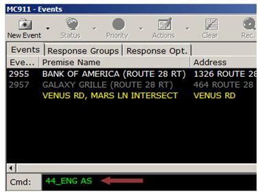
- The Command Line lets you enter commands by typing, instead of clicking on buttons. It used abbreviations for each of the main commands. For more information, please refer to the list of standard abbreviations.
An Example of the Command Line
This is an example of how the Command Line is used. In the example above, the user has typed the short cut for At Scene, and the names of the Units they wish to be placed in that status.
6. Locating Nearby Hydrants
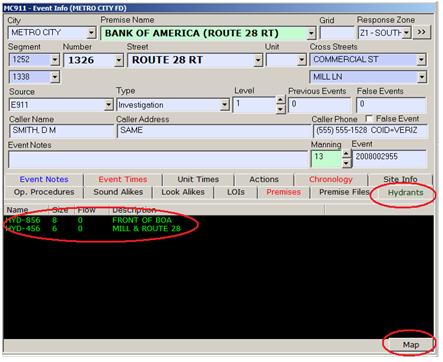
- The hydrants tab in the main event info display area lets you quickly retrieve a listing of the hyrants near the currently selected incident. Clicking on the “Map” button in the lower right hand corner of the listing will display the hyrant icons on the map in the actual locations.
An Example a Hydrant Listing
7. Listing Related Premises
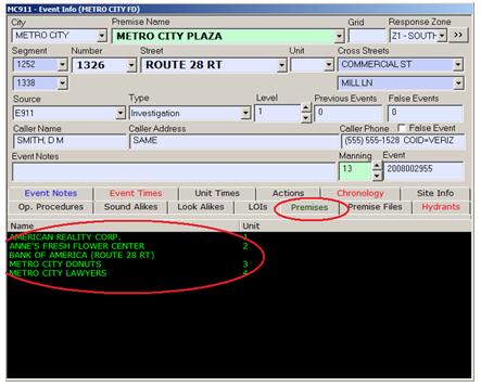
- The Premises Tab in the main event info display area allows you to display a listing of all the other locations at you current address. You can change the call location to any one of these locations simply by clicking on the item in the list.
An Example a Related Premise Listing
8. View Premise Related Media Files
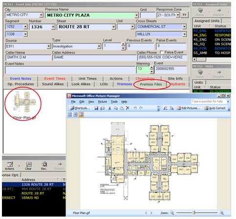
- The Premises Files Tab in the main event info display area allows you to display a listing of all currently assigned media files (e.g. floor plans, reponse documents) for your current address. You can launch the file in its native viewing application by clicking on the thumbnail image in the file listing area.
An Example a Related Premise Media File
9. Display Operating Procedures
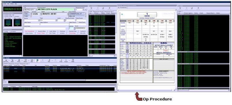
- The Operating Procedures Tab (which is often given a window of its own to display information) will automatically display any operating procedure associated with a call based on response zone, call type or a combination of these and many other factors.
An Example a Operating Procedure File
Section VIII – Commonly Used Headers
These are some of the standard headers that are found in the Events, Units and Assigned Units tabs. Information under these headers is sortable by clicking on the heading in question.
Events Headers
Event Number: Shows the numbers assigned to the active events.
Type: Event Types, as defined in the field.
NB: An “@” symbol in this field indicates that the event is physically NEARBY the selected event.
Status: The current status of the event (Dispatched, Enroute, etc.).
Priority: Generally High, Medium, or Low. The default is generally medium.
Premise Name: The name location of the event.
Address: The street address of the event.
Timer: Displays any active timers.
Agency Name: Displays who the responding agency is for the selected event.
Units and Assigned Units Headers
Unit: Displays Unit designations (i.e., “P1”).
Primary Agency: Displays the primary agency each unit is assigned to.
X: Provides the current X coordinate (If GPS is enabled).
Y: Provides the current Y coordinate (If GPS is enabled).
Responding Agency: Displays which agency is the default responding agency for a given event.
Event: Displays the event number.
Status: Displays the status of the unit in question (i.e., Dispatched, Enroute, etc.).
Timer: Displays any active timers.
Base Response Group: Indicates which response group a given unit is assigned to.
Section IX - Other Event Info Options
What follows are some system functions that can help in making the event response process quicker and more effective.
Remember: Black tabbed displays mean there is no information in that specific tab. Blue tabbed displays mean that there is information in the tab, and red tabbed displays mean that the information has changed since the last time you looked at it.
1. Look Alikes Tab
- The Look Alikes tab displays any addresses that look similar to the address (ie, Queen Street and Queen Avenue). If there are any Look Alikes for a selected event, the tab will turn red. Clicking on the tab will reveal the information.
2. Sound Alikes Tab
- The Sound Alikes tab displays any addresses that look similar to the address (ie, Smyth Street and Smith Street). If there are any Sound Alikes for a selected event, the tab will turn red. Clicking on the tab will reveal the information.
3. Site Info Tab
- The Site Info tab reveals any important information about the premise or address at which the event is occurring. If there is any site info for a selected event, the tab will turn red. Clicking on the tab will reveal the information.
4. Premise Tab
- The Premise tab is used when there are multiple units or premises at an address (such is the case with malls, hospitals, apartment buildings, etc.). If there is any site info for a selected event, the tab will turn red. Clicking on the tab will reveal the information.
- The tab will display a list of premises. Selecting the premise will set the event at that premise (the Unit field will be set to the proper premise number)
5. Ops. Procedures and LOI Tabs
- Operating Procedures are standardized strategies for dealing with specific event types. Locations of Interest are areas close to the event that might be important. If there is information for these tabs, they will be red (if you haven’t yet looked at them) or blue (if you have).
- To access operating procedures, select the appropriate event in the Events window and click on the Ops. Procedures tab.
- To access LOI’s, click on the LOI tab, and click the Show Info button. Click the MAP button to display the location of the LOI on the map.
Section X - Other Windows
These are other functions that may be important in the Event Management process.
1. Clock
- The clock window displays the local time.
2. System Log (System Information)
- This window displays how much of your workstation’s resources are being used. Very high levels of resource use may result in a slowdown in performance. If this happens, please notify the system administrator.
3. Window Manager
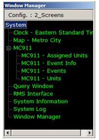
- Because a large number of windows may be open at once, some of the less-used ones (such as the Query window) may be hidden from view.
- To display a hidden window, simply select the window you wish to view in the list in the Window Manager window.
A Close-Up of the Window Manager Window
4. RMS Interface
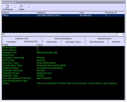
- The RMS interface window will display the relevant RMS information about the current location. This will often include such information as contact lists, building and preplan information.
- The RMS interface allows the user to link dynamically to any database containing property information. The user can then create their own windows tab-based category views and select the information to be displayed in each of these tabs. The EM Center can then be configured to alert the operator with a flashing indicator when information about a premise is available.
An Example of the RMS Interface Module
The RMS Module lets you access many types of information that might be stored in your RMS system, such as contacts, building info, permits, pre-plans and much more.
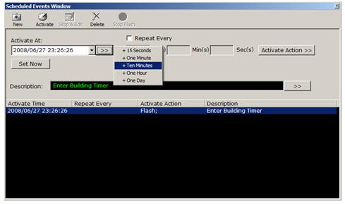
5. Scheduled Events
- The Scheduled Events window enables you to pre-schedule an event or system action. To pre-schedule an action or event, click on the New button, and type in the description in the Description field.
- Click on the Activate button, and determine the time you want the event to activate.
- Click on the Activate Action button to select the appropriate option as to what the event will be.
An Example of the Scheduled Events Module
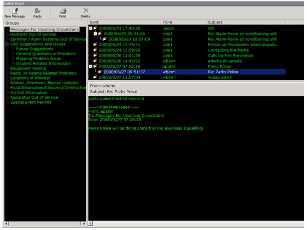
6. Bulletin Board
- The Bulletin Board window is the system’s internal messaging system, and allows users to communicate by reading and sending text-based messages.
- To view a message, select the appropriate group or sub-group in the Group display and select the appropriate message from within the group or subgroup in the Available Message display
- To send a message, click the New Message button, type in the group you wish to post to, and the subject. If you require a list of available groups, or wish to post to more than one group, hit the Groups button. Once completed, click on the Send button to send, or the Cancel button to cancel.
An Example of the Bulletin Board Module, with a Message Group Highlighted
Appendix – Command Line Shortcuts
NOTE: You can go to the command line at any time by pressing the Shift and Escape keys (Shift+Esc) at the same time or by placing your mouse in the command line box.
NOTE: You can go back and forth in the command line history (to recall and repeat commands) by using the arrow up and arrow down keys
1) AA - ACTION ABBREV
This command lets you enter actions directly in the command line, using the initials (first letters) of the Action.
Example: The action “Police On Scene”, which is abbreviated to “POS”. This command is used when the event you wish to add an action for is already selected in the Event window.
2) AA+ - ACTION ABBREV+
This command lets you enter actions directly in the command line, using the initials (first letters) of the Action, as in 1) above. The difference however, is that you use it when you wish to add an action to an event that you do not have selected.
Example: After the plus, you type in the event number, and THEN the abbreviation. Using the example above, it would look like “AA+ 12345 POS”.
3) AF - ACTION FULL
This command lets you enter actions directly in the command line, typing out the entire action.
Example: To use the example cited in 1) – Police On Scene, you would type AF Police On Scene.
4) AF+ - ACTION FULL+
This command lets you enter actions directly in the command line, typing out the entire action.
Example:To use the example cited in 1) – Police On Scene, you would type AF Police On Scene. The difference however, is that you use it when you wish to add an action to an event that you do not have selected. After the plus, you type in the event number, and THEN the abbreviation. Using the example above, it would look like “AA+ 12345 Police On Scene”.
5) AS - ASSIGN
This command lets you manually assign units to an event.
Example: Simply type AS and then the call signs of the units you would like to assign – i.e., AS P101 P102 E99
6) CD – CLEAR DISPLAY
This command will clear the display of the current event being viewed
Example: CL will clear the display of the current event being viewed
7) CE – CREATE EVENT
This command will create a new event for the agency specified.
Example: CE H will create a new event for the Halton Hills Fire Service.
8) DL – DOWNGRADE LEVEL
This command will downgrade the alarm level of the current event or the event specified*
Example: DL will downgrade the alarm level of the current event
Example: DL 109 will downgrade the alarm level of the event that ends in number “109”
9) EIP - EVENT INFO PREMISE
This command takes you directly to the Premise field in the Event Info section, letting you modify or search for the name as appropriate.
10) EN – EVENT NOTE
This command will add an event note to the current event
Example: EN VSA will add “VSA” as an event note to the current event
11) EN+ – EVENT NOTE PLUS EVENT SPECIFIER
This command will add an event note to the event specified*
Example: EN+ 109 VSA will add “VSA” as an event note to the event that ends in number “109”
12) ES – EVENT STATUS
This command will change the event status of the current event or the event specified* if the change is allowed
Example: ES CN will cancel the current event
Example: ES 109 CN will cancel the event that ends in number “109”
Possible Event Status Specifiers are:
AC – Accepted
CD – Closed
CN – Canceled
*All other event statuses are system controlled
13) EX – EXIT SYSTEM
This command will exit the EME
Example: EX will exit the EME
14) LO – LOG OFF
This command will log off the current user
Example: LO will log off the current user
15) ME – MAP EVENT
This command will center the map on current event or the event specified*
Example: ME will center the map on the current event
Example: ME 109 will center the map on the event that ends in number “109”
16) MU – MAP UNIT
This command will center the map on the unit specified+
Example: MU P720 will center the map on unit P720
17) RC – RECOMMEND
This command turns on or off recommendation for the current event if the event has a status that allows recommendation
Example: RC will activate recommend for the current event if the current event has a status that allows recommendation and the recommend function is not active
18) SE – SELECT EVENT
This command will select and display the event specified*
Example: SE 109 will select and display the event that ends in number “109”
19) SEP – SELECT EVENT BY POSITION
This command will select and display the event specified by its position in the event list
Example: SE 1 will select and display the first event in the event list
Example: SE 3 will select and display the third event in the event list
20) TABS – SETS THE FOCUS TO THE EVENT INFO TABS (TB)
This command will set the focus to the event info tabs (Event Notes, Event Times, Unit Times, etc) so that the user can scroll through them using the arrow keys
Example: TABS will set the focus to the event info tabs
21) US – UNIT STATUS
This command will change the status of the unit specified if the status change is allowed
Example: US P720 OS will set the status of unit P720 to Out of Service
Example: US P720 T740 C701 IQ will set the status of unit P720, T740 and C701 to In Quarters
Possible Unit Status Specifiers are:
DP – Dispatched
EN – Enroute
TB – Turn Back
RR - Reroute
AS – At Scene
CL – CLEAR
RT – Returning
IQ – In Quarters
OS – Out of Service
IS – In Service
22) UL – UPGRADE LEVEL
This command will upgrade the alarm level of the current event or the event specified*
Example: UL will upgrade the alarm level of the current event
Example: UL 109 will upgrade the alarm level of the event that ends in number “109”
- When specifying an event number you only have to enter enough of the last digits of the event number so the system can tell when event you wish to select (i.e. if you have events 2003000045, 2003000109, 2003000052 – and you wish to select 2003000109 you can type “9” or “109”)
+ A GPS system must be in use for this function to work
23) ZI - ZOOM IN
This command lets you zoom in a specified amount on the map. The amount you zoom in is specified by a number.
Example: Typing ZI 50 will magnify the map view a certain degree, but less than ZI 100
24) ZO - ZOOM OUT
This command is the opposite of above, letting you zoom out a specified amount on the map. The amount you zoom out is specified by a number.
Example: Typing ZO 50 will zoom out the map view a certain degree, but less than ZO 100

